A Revolutionary Idea Requires a Revolutionary Approach
See how the design team for Baxter Arena utilized computational design approaches for a wide array of project-based studies, constructing tools to explore a wide range of variables related to site planning, architectural massing and exterior design. Computation allowed the design team to be thorough and precise during the conceptual development stage when problems tended to be non-linear and open-ended.
As the University of Nebraska Omaha’s (UNO) main building for large events, the new Baxter Arena is a physical representation of UNO’s athletic brand. The facility, which anchors the southern extent of the campus, is designed to serve multiple activities, weaving together function and aesthetics.
HDR and Lempka Edson Architects completed master planning and architectural and engineering design services for the new arena. It offers a full-spectrum student life experience, reinforces the brand for UNO Athletics and engages Omaha’s vibrant Aksarben Village culture.
Sketch to Form
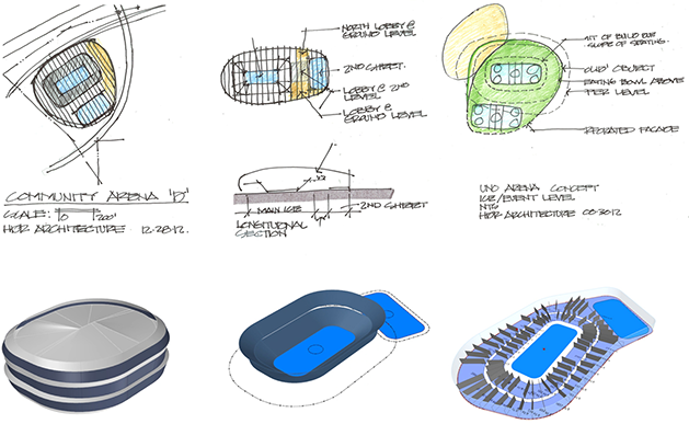
One of the successful ways computational design was implemented during the concept phase was by developing parametric “throw-away” models. We developed an iterative process of creating concept sketches, and then built on-the-fly parametric models. Similar to building a CAD drawing from a sketch to test scale and viability, the parametric model allowed the team to flex the model, test options and then go back to sketching.
One of the biggest misconceptions about computational design is that it replaces the sketching process. Some projects have the ability to be either repetitive or driven by certain parameters. For example, the typology of an arena dictates the overall height and shape of the seating bowl. In the end, flexing the location of the community ice provided many different options in internal programming adjacencies and external appearance as one approaches the facility.

Maximize Glass, Minimize Sunlight
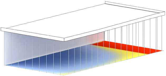
As the Baxter Arena design developed, the community ice became a major feature, serving as an open front entry to what is typically a concealed box. Accommodating glass around an ice rink required extensive daylight and energy models to be developed throughout the design development phase. Variables that impacted the models included roof and angle height, overhang depths, solid-so lito-glazing ratios on the south façade and material configurations. These variables were adjusted iteratively and provided quick feedback to the team. The result was a design that maximized the amount of glass and minimized the amount of direct sunlight on the ice.

Connecting Design to Production
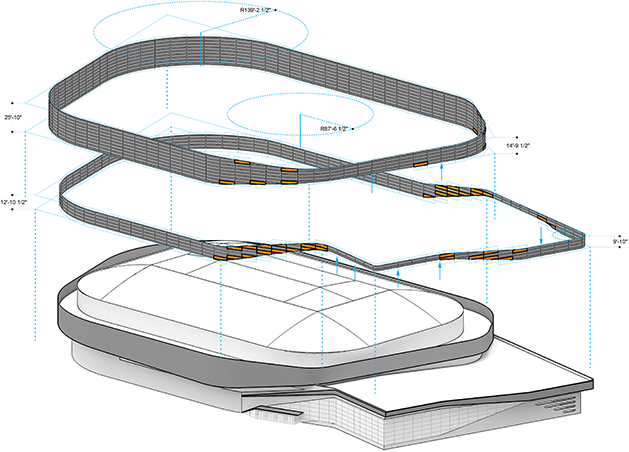
As the design and program began to take shape, developing the façade became critical. Most projects hit a point where the schematic design is either completed or close to completed when the production model (Revit model) begins. During this phase, the Revit model is populated with floors, walls, rooms and doors. One of the more challenging things to build in Revit is a façade, especially if it’s curved with custom panels. It is relatively easy to move walls and rooms around as the design and program change, but it is much more difficult and very time-consuming to update a custom façade in Revit with traditional workflows. Nate Miller, our partner while at CASE, developed a custom workflow for HDR to allow the team to connect the design model from Rhino to our production model in Revit. This process allowed the design team to iterate program and design options and link the concept and production models. In the end, we were able to control a consistent framework for the façade to be developed.


